Flux Marine for X Shore
A 250 kW inboard electric drivetrain capable of accelerating a 2.5 ton boat from 0-55kph in 3.5 seconds, built on outboard-proven technology in half a year.
Flux Marine, for X Shore
The people- CTO, X Shore
- CEO, X Shore
- Controls engineering team, X Shore
- CEO, Flux Marine
- Me, engineering lead
The brief
X Shore engaged Flux Marine to develop a modular, drop-in propulsion system for its full product line, including the XS1 and the Eelex 8000. Flux Marine builds electric outboard motors. Adapting Flux's marine-proven propulsion tech and battery storage solutions to the new hulls in a novel inboard configuration rapidly became the program's focus.
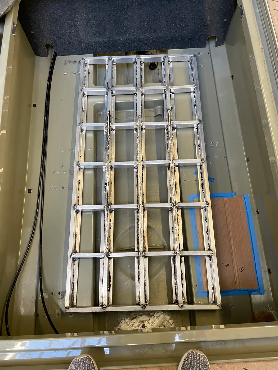
Challenges lay in architectural revision and system design. X Shore required a system as quiet as its demonstrator, which used a hand-made gearbox, valued at about $25,000, that tended to fail under peak mechanical load. Interfaces spanned four engineering domains: mechanical (gearbox design and shaft integration), thermal (design and integration of a closed-loop glycol-filled in-water heat exchanger), electrical (marinization and mounting of thousands of kilograms of battery capacity), and controls (X Shore’s existing CAN bus and power control algorithms, with firmware integration led by X Shore’s controls engineering team).
System architecture
Scroll sideways to see the whole diagram.
Heavy orange lines carry high-voltage and shore power. Thin orange lines carry 12 V power. Dashed lines carry data, sensing and hardwired safety signals. Heavy neutral lines are mechanical. Dotted lines carry coolant. The shaded band is below the waterline.
Interfaces
| ID | End A | End B | Type | Description |
|---|---|---|---|---|
| 1 | Helm | Vessel control unit | Data, CAN | Throttle position, drive direction and mode selection pass to the vessel control unit, and state of charge, power, temperature and fault data return to the helm display. |
| 2 | Battery management system | Vessel control unit | Data, CAN | The BMS reports state of charge, cell limits and the allowed charge and discharge power, and receives contactor close and open requests. |
| 3 | Onboard charger | Vessel control unit | Data, CAN | The charger reports shore connection and charge status, and receives a charge current limit derived from the BMS limits. |
| 4 | Vessel control unit | Inverter | Data, CAN | Torque requests from X Shore’s power control algorithms pass to the inverter, and motor speed, temperature and fault status return. |
| 5 | Battery management system | Battery pack | Sensing | Cell voltage, module temperature and pack current are measured in each module and returned to the BMS. |
| 6 | Battery management system | HV junction box | Control, hardwired | The BMS drives the main contactor and precharge relay coils, and reads contactor state, insulation resistance from the insulation monitor, and the state of the HV interlock loop that runs in series through every HV connector. |
| 7 | Helm E-stop | HV junction box | Safety, hardwired | The E-stop switch and the kill cord are wired in series with the contactor coil supply, so that either one opens the main contactors without software action. |
| 8 | Battery pack | HV junction box | High-voltage DC | Pack positive and negative leads through the main fuse to the main contactors. |
| 9 | HV junction box | Inverter | High-voltage DC | Traction supply to the inverter DC link, which the precharge circuit charges through a resistor before the main contactor closes. |
| 10 | HV junction box | DC-DC converter | High-voltage DC | Fused supply to the DC-DC converter. |
| 11 | Onboard charger | HV junction box | High-voltage DC | Charge current to the pack through a dedicated charge contactor. |
| 12 | Shore power | Onboard charger | AC power | AC shore power through the shore inlet. |
| 13 | DC-DC converter | 12 V system | Low-voltage DC | Regulated 12 V supply that charges the 12 V battery and feeds the control electronics, the helm and the vessel loads. |
| 14 | 12 V system | Coolant pump | Low-voltage DC | Fused 12 V supply to the coolant pump motor. |
| 15 | Inverter | Motor | Three-phase AC | Variable-frequency drive current, up to 250 kW. |
| 16 | Motor | Inverter | Sensing | Rotor position and winding temperature signals for motor control and thermal derating. |
| 17 | Coolant pump | Inverter | Coolant | Glycol supply to the inverter cold plate. |
| 18 | Inverter | Motor | Coolant | Glycol flow from the inverter cold plate to the motor cooling jacket. |
| 19 | Motor | In-water heat exchanger | Coolant | Heated glycol from the motor jacket to the heat exchanger. |
| 20 | In-water heat exchanger | Coolant pump | Coolant | Glycol return to the pump after the heat exchanger rejects heat to the sea water. |
| 21 | In-water heat exchanger | Hull | Mechanical | Mounting and sealed hull penetrations for the glycol supply and return lines. |
| 22 | Motor | Gearbox | Mechanical | Shaft coupling and a common mounting flange. |
| 23 | Gearbox | Shaft and propeller | Mechanical | Output shaft torque and propeller thrust, through the shaft seal in the hull. |
| 24 | Motor and gearbox | Hull | Mechanical | Isolation mounts on a bed in the modified hull, which react drive torque and propeller thrust. |
| 25 | Battery pack | Hull | Mechanical | Mounts and load path for thousands of kilograms of battery modules. |
How it unfolded
- Months 1 to 4X Shore commissioned a modular, drop-in inboard drive from Flux Marine. The two companies formed a joint engineering team, and the program built up slowly through planning.
- ArchitectureThe system architecture and the high-level control schemas were defined, setting the interfaces between the drivetrain, the cooling loop, the battery and X Shore’s control system.
- LogisticsBoats and X Shore personnel were moved across international borders and through customs.
- CheckpointsCustomer checkpoints with X Shore were set against technology readiness levels (TRL).
- Months 5 and 6Most of the hardware development happened in the final two months. The team designed the gearbox and sourced its manufacturer, developed the battery modules, and designed the closed-loop heat exchanger.
- Hull and fabricationThe hulls were modified, including below the water line, and the mechanical subsystems were fabricated.
- Integration and testThe subsystems were integrated. The drivetrain was instrumented and tested for thermal and NVH performance.
- DeliveryThe prototypes were delivered to X Shore and entered testing.
- RefinementThe subsystems were refined, based on data from joint testing by X Shore and Flux Marine.
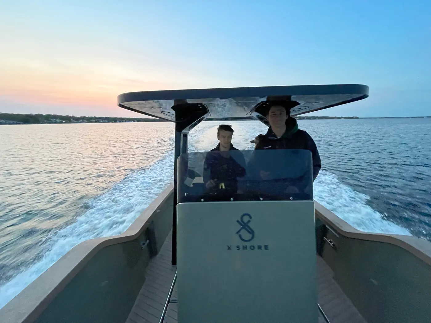
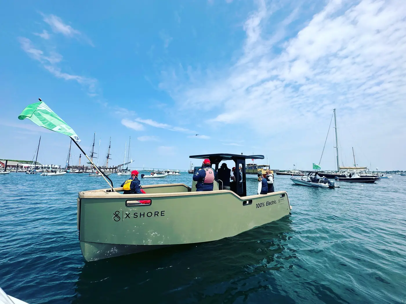
- Customer acceptanceX Shore accepted the systems in Newport, Rhode Island, during the scheduled stopover there of The Ocean Race, the round-the-world sailing race formerly known as the Volvo Ocean Race. The Eelex 8000 and the XS-1 served as VIP shuttles around Fort Adams and between the New York Yacht Club and Fort Adams.
What I did
- Program management and client relationsLed the joint engineering program across Flux Marine and X Shore. Engineering point of contact for X Shore’s leadership and controls engineering team.
- Architecture and controlsIn-depth system architectural design and high-level development of control schemas.
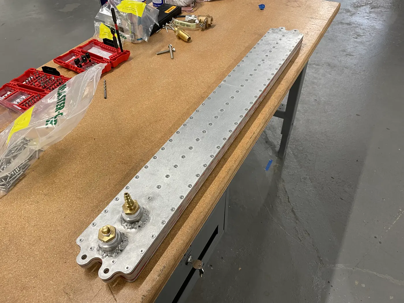
- ThermalIn-water closed-loop heat exchanger design.
- Drivetrain and hullGearbox design and manufacturer sourcing. Hull modifications, including below the water line, to suit prototype implementation.
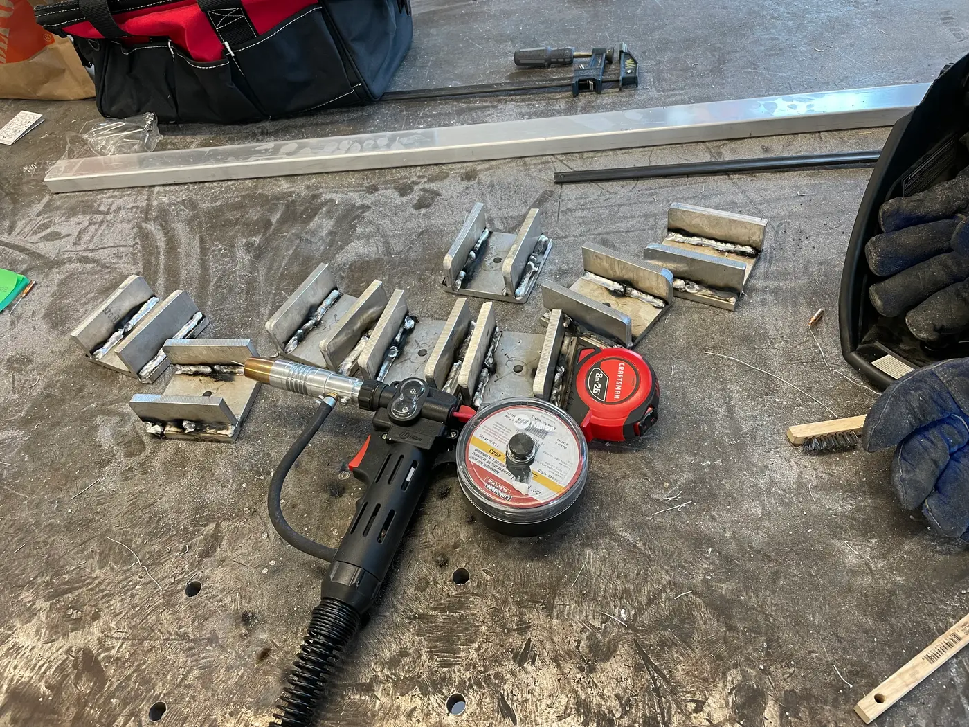
- Battery and mechanicalBattery module development and mechanical integration. Mechanical subsystem design and fabrication.
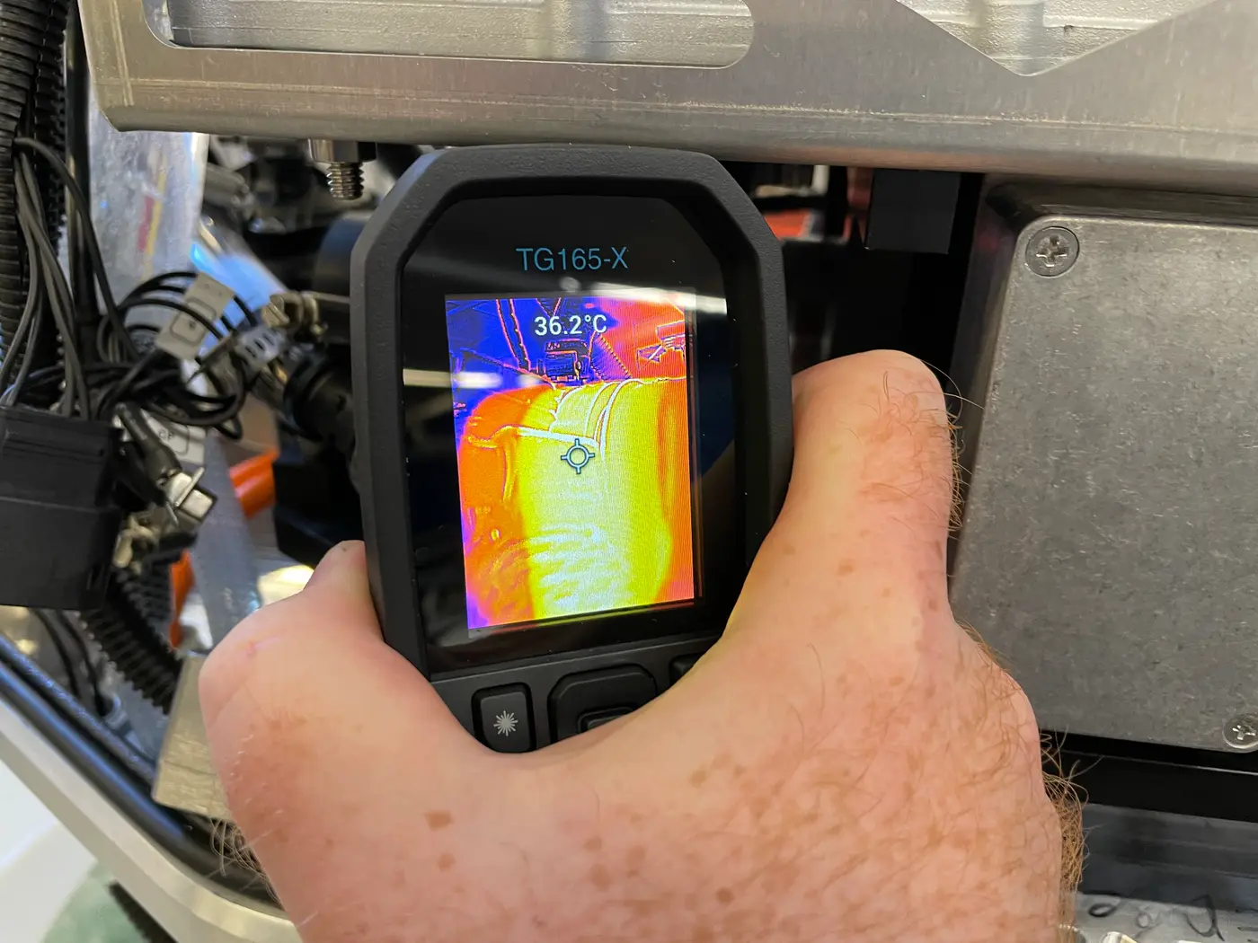
- Testing and validationHeat exchanger validation and testing. Sensorization of drivetrain assembly for both thermal and NVH debugging/isolation testing. Joint X Shore and Flux Marine testing after delivery.
- Integration and after deliveryFinal subsystem integration, and post-delivery iterative improvement based on the joint test data.
Decisions
- Cooling. X Shore’s existing system drew raw seawater through the cooling loop. It worked only while the water stayed clean and the loop was flushed often. In service, the loop needed maintenance about every ten hours to clear salt corrosion, micro-organisms and debris. The team chose a hull-mounted heat exchanger instead, and it worked. It had a hydrodynamic cost: the exchanger sat in the water flow at speed, and the wetted area it needed made it large and obtrusive. Drag reduction matters more for electric boats, which recharge over hours at specialized charging stations, than it does for traditionally-propelled vessels, which refuel at standard fuel docks in moments.
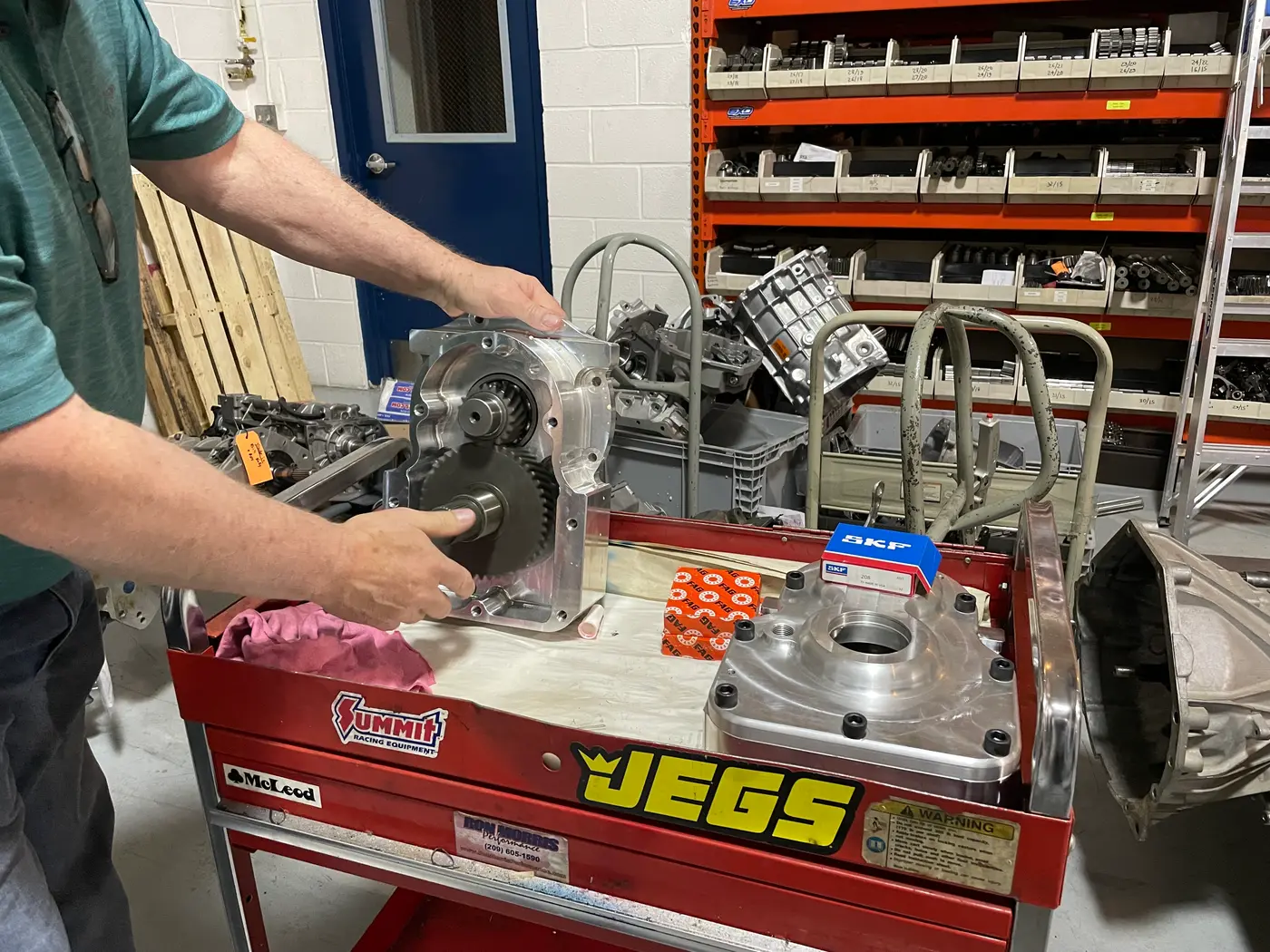
- Gearbox. The team worked with a geartrain manufacturer in Pennsylvania that had direct experience in high-horsepower drag racing. The new gearbox was louder than the demonstrator’s, but far more robust, and it needed no external cooling, which the original gearbox had needed in large amounts. Thermal tests during the break-in of the prototype units showed higher temperatures than intended, so the team changed the oil mixture. The team reduced the noise by specifying the gearbox oil more tightly and by adding insulation to the walls of the engine compartment. NVH test data then showed X Shore that the system met the NVH goals of its original system, within a reasonable margin.
- Commercial parts. X Shore’s earlier system was built primarily from custom components. The new system used mostly commercial off-the-shelf parts. It was less elegant, but more durable and easier to repair during in-field servicing.
The delivered system proved the potential of a significant part reduction and engineering overhaul. Consequently, X Shore’s margin substantially improved as a function of a reduction in part count and cost. X Shore then refined the design to better suit proprietary automated manufacturing processes at its home factory in Sweden.
Core engineering principles and the rudimentary system architecture of the outboard system could be rebuilt into a durable and modular inboard system at vastly higher power outputs.
Multi-disciplinary hardware programs succeed or fail at the limits of team and system structure. I held the system architecture and team organization while working hands-on in the subsystems and directly with the client, so interface decisions stayed with the engineer accountable for ensuring integration and program success.